nucleOS
nucleOS is my attempt at creating a lightweight embedded operating system.
The development of this operating system is done on a STM-Nucleo 144 development board which is running an STM32-H743ZI microprocessor.
The H743ZI is the highest specced version of the STM32 chips which allows for every feature offered by STM32 to be programmed.
February 1st, 2022
NucleOS Updates
I haven't written an update for this project in years, but that's also because I haven't work on it in years.
In its current state, the original ARM port of NucleOS contained:
- Basic tasking
- Round robin based task-switching
- Dynamic stack allocation
- System Drivers
- GPIO
- USART
- SPI
- Serial (USART over USB)
- Very basic system utilities
- Queue implementation
- Clock-based delays
- IRQ controls
While this really isn't a lot of features, it was still an incredibly valuable learning experience. I learned an endless amount of things about OS development while working on this project, and it's lead me to understand embedded systems far more than I could've hoped.
x86 Port
In an attempt to make the system more portable, I created a new branch of the code to make it cross-platform. I started working on the x86 portion of the code first, but I ran out of time while working on it. I learned a lot about x86 while developing this new port, mostly how x86 is a disgusting mess that has too many ways to complete a task, all of them incorrect.
While working on this port, I learned a lot of other useful skills:
- Custom GCC/G++ toolchain ports
- x86 booting magic (literally a magic number)
- Interfacing with bootloader
- Interfacing with BIOS
- Interfacing with UEFI
- C Library porting
- PDCLib
- Newlib
- C Runtime
- How crti, crtn, crt0, etc.. Work to initialize a program/kernel
- C ABI for x86
- Fun little features like stack smashing detection
March 20th, 2019
Serial over USB
Previously I had some issues getting USART over USB to work with this project.
The issue was a rather basic issue caused by a simple arithmetic mistake on my part.
On the STM32 Nucleo-144 H7 board, USB over serial is done over USART3, using
GPIO pins PD8 and PD9 for RX and TX respectively. Since each GPIO pin can be
used for a multitude of peripherials (SPI, I2C, USART, etc..), both the RX
and TX pins must be told they are going to be used for USART, and not any
other interface. This was done using the function GPIO_AlternateMode,
which can set any GPIO port to its desired mode.
For pins PD8 and PD9, the alternate mode for USART3 is mode 7. Which means
that both pins needed an alternate mode of 7. At the time, the function
GPIO_AlternateMode had the following definition:
void GPIO_AlternateMode(GPIO_TypeDef* port, uint32_t pin, uint32_t mode)
{
    /*
     * Pins 0-7 use AFRL and pins 8-15 use AFRH.
     * By dividing the pin by 8 we can get 0 for 0-7 and 1 for 8-15.
     * This will give the selection value for either AFRL or AFRH
     */
    port->AFR[pin/8] &= ~(0xF << (pin % 8)); // Clear pin AF
    port->AFR[pin/8] |= mode <<  (pin % 8);  // Set pin AF
}
These two lines are where the issues laid:
    port->AFR[pin/8] &= ~(0xF << (pin % 8)); // Clear pin AF
    port->AFR[pin/8] |= mode <<  (pin % 8);  // Set pin AF
Each GPIO pin can have 16 total functions, meaning that each pin needs 4 bits in order to signify its current function (0-15). The issue with these two lines of code is that they only gave each pin 1 bit to signify its function instead of 4 bits.
Using this function in this incorrect state, the following happened:
Writing 7 to pins PD8 and PD9 wrote the value 0xF to AFRH instead of the
value 0x77. This is because the value 0b0111 (0x7) has to be written to
bits 0-3 (pin 8) and pins 4-7 (pin 9). Which would give the AFRH register
a value of 0b01110111 (0x77). With the original code, each pin's bits were
only shifted once instead of 4 times, so the AFRH was given the value 0b1111.
This result was obtained from pin 9's alternative value: 0b0111 was shifted
once to get: 0b01110 instead of 4 times like it was supposed to: 0b01110000.
In order to fix the alternate mode function, it was changed to the following:
void GPIO_AlternateMode(GPIO_TypeDef* port, uint32_t pin, uint32_t mode)
{
    /*
     * Pins 0-7 use AFRL and pins 8-15 use AFRH.
     * By dividing the pin by 8 we can get 0 for 0-7 and 1 for 8-15.
     * This will give the selection value for either AFRL or AFRH
     *
     * Shifts are multiplied by 4 because each alternate function is
     *  4 bits wide.
     */
    port->AFR[pin/8] &= ~(0xF << ((pin % 8)*4)); // Clear pin AF
    port->AFR[pin/8] |= mode <<  ((pin % 8)*4);  // Set pin AF
}
What makes this code correct is changing the two main lines of code to multiply the shifting values by 4.
USART3 Interrupt Handling
After fixing the GPIO alternate function body, serial over USB worked properly, but the only way it could be used was through polling. To avoid this and make the serial faster, I created a USART3 interrupt handler for sending and receiving data over the USART3 bus. This required me to use the circular queues implemented previously.
The serial interrupt has a basic structure like so:
function USART3_IRQHandler()
    Interrupts_Disable
    if RecievingBytes then
        EnqueueByte from bus
    endif
    if SendingBytes then
        if SendingQueueSize > 1 then
            PopQueue and send byte
        if SendingQueueSize == 0 then
            Disable tx interrupt
    endif
    Interrupts_Enable
January 17th, 2019
Creating a more powerful GPIO library
GPIO pins are a very import part of any microcontroller as they allow it to interact with outside peripherals. They are also able to be controlled by other systems on the board, e.g., SPI, I2C, USART, etc..
Previously I had a few functions to control GPIO, but that was only for setting GPIO mode and type. In order to do any other GPIO control, it was all done manually, i.e., setting register bits manually.
There were a couple of design choices to be made with with the architecture of this GPIO control. It could be done by:
- Making a variable (most likely a structure) that held the GPIO data that could be modified to change GPIO settings.
- Using pure functions to control GPIO settings and set pin values.
- A small mix of both. This would mean creating a GPIO variable to store GPIO data and using functions to either update the hardware to follow these changes or update the variable itself.
In the end, the choice was made to use pure functions in order to control the GPIO pins. The reason being is that this won't waste memory like variables will. This will also make changes to the GPIO pins nearly instantly as the hardware is being changed directly instead of having to update the hardware to match variable values.
The downside of this method is that every time we want to modify GPIO hardware
we have to call a function using a GPIO_TypeDef and a pin to modify, and this
data can't easily be saved in a variable.
The goal with these functions was to provide near full GPIO control, but give a more obfuscated way of accessing them.
This meant that a function had to be created for nearly every GPIO register.
| GPIO Register | Use |
|---|---|
| GPIO_MODER | Set pin modes |
| GPIO_OTYPER | Set pin types |
| GPIO_OSPEEDR | Change pin speeds |
| GPIO_PUPDR | Set/remove pull-up or pull-down resistor |
| GPIO_IDR | Current input state of all pins |
| GPIO_ODR | Current output state of all pins |
| GPIO_BSRR | Pin set/reset register |
| GPIO_LCKR | Port configuration lock |
| GPIO_AFR | Set pin alternate functions |
One of the functions made previously was the GPIO_Mode() functions.
Two functions very similar to this would be the GPIO speed modification
function, GPIO_Speed(), and the pull-up/pull-down resistor modification
function, GPIO_PUPD().
Both of these functions use two bits per pin to set the given settings. So that can be done with the following code used previously:
port-><REG> &= ~(3 << (2 * pin));
port-><REG> |= set << (2 * pin);
This lets us make a basic function for both the speed and pull-up/pull-down resistor settings:
void GPIO_Speed(GPIO_TypeDef* port, uint32_t pin, enum GPIO_SPEED speed)
{
    port->OSPEEDR &= ~(3 << (2 * pin));
    port->OSPEEDR |= speed << (2 * pin);
}

void GPIO_PUPD(GPIO_TypeDef* port, uint32_t pin, enum GPIO_PUPDR pupd)
{
    port->PUPDR &= ~(3 << (2 * pin));
    port->PUPDR |= pupd << (2 * pin);
}
The enums for both of these are very similar to that of the GPIO mode function:
enum GPIO_SPEED {
    LOW = 0,        /**< Low speed */
    MEDIUM = 1,     /**< Medium speed */
    HIGH = 2,       /**< High speed */
    VERY_HIGH = 3   /**< Very high speed */
};

enum GPIO_PUPDR {
    NO = 0,         /**< No pull-up/pull-down resistor */
    UP = 1,         /**< Pull-up resistor */
    DOWN = 2        /**< Pull-down resistor */
};
As showed by the given code examples, these registers function very similarly to the GPIO mode register, so their programming is very similar.
The next thing that needed to be done with GPIO was setting the pin types. Each pin has a type that is either push/pull or open/drain. Setting this type will change both power output and speed. Usually push/pull is the better option, but in certain cases, like if GPIO are to be used to create a "wired-or" then the open/drain mode is good because it allows for multiple outputs to be shorted together.
Since there are only two types a pin can be set to, push/pull and open/drain, each pin only needs a single bit in the GPIO_OTYPER register to set its type. The code for setting the pin type (with included enum) looks like so:
enum GPIO_TYPE {
    TYPE_RESET = 0, /**< Resets the pin to default type (push/pull) */
    PUSH_PULL = 0,  /**< Sets the pin to push/pull mode. */
    OPEN_DRAIN = 1  /**< Sets pin to open/drain mode. */
};

void GPIO_Type(GPIO_TypeDef* port, uint32_t pin, enum GPIO_TYPE type)
{
    port->OTYPER &= ~(1 << pin);
    port->OTYPER |= type << pin;
}
Another important function of GPIO ports is the ability to get controlled by external controllers, e.g: USART, SPI, I2C.
Since these pins will no longer be controlled by the user's code, they will
placed into "alternate function" mode. This alternate function needs to be
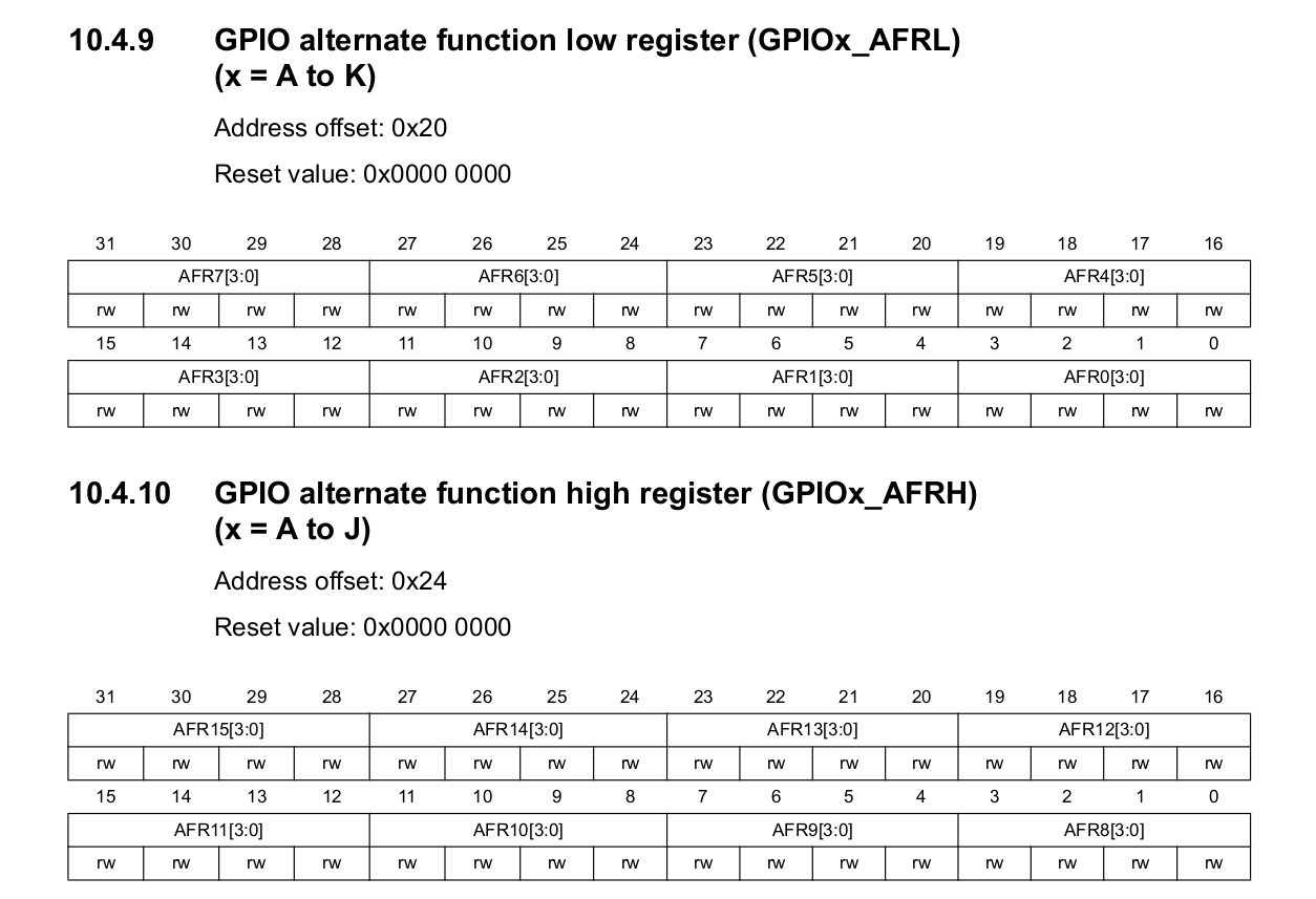
set using the GPIO alternate function register, GPIO_AFR.
The GPIO_AFR data was actually accessed by modifying two different
registers. GPIO_AFRL and GPIO_AFRH. Figure 1 shows the AFR registers' data
layout.
Since the GPIO pins are split between two different registers, we need to use a little trick to set the alternate function of a GPIO pin. The alternate function selecting code looks like so:
void GPIO_AlternateMode(GPIO_TypeDef* port, uint32_t pin, uint32_t mode)
{
    /*
     * Pins 0-7 use AFRL and pins 8-15 use AFRH.
     * By dividing the pin by 8 we can get 0 for 0-7 and 1 for 8-15.
     * This will give the selection value for either AFRL or AFRH
     *
     * Shifts are multiplied by 4 because each alternate function is
     *  4 bits wide.
     */
    port->AFR[pin/8] &= ~(0xF << ((pin % 8)*4)); // Clear pin AF
    port->AFR[pin/8] |= mode <<  ((pin % 8)*4);  // Set pin AF
}
This function isn't too difficult to understand, although it is a little tricky to wrap your head around at first.
Settings GPIO Pin values
Now onto the most important part of this whole ordeal. Setting/receiving the I/O data from each pin.
Sending and receiving data over a GPIO pin is actually easier than the rest of the GPIO operations once you fully understand it. Once again, I'm going to recommend reading this article about the STM32 GPIO pins, as this is where I learned how to use this pin I/O registers.
Sending over GPIO is done using two registers, BSRR and BSR.
The BSRR register is used to set pin states to high, and BSR is used to reset
pins.
NOTE: While this is true for most STM32 processors, the STM32 H7 doesn't
use the BSRR and BSR registers, instead it uses BSRRL and BSRRH respectively.
Using these registers is very simple. Each bit of each register corresponds to
the register this operation will occur on. e.g.: Setting bit 3 high in the
BSRRL register will set pin 3 high, and setting pin 7 to high in BSRRH will
reset pin 7 to low.
This means we can make two simple functions to and reset GPIO pins:
inline void GPIO_SetPin(GPIO_TypeDef* port, uint32_t pin)
{
    port->BSRRL |= (1 << pin); // BSRRL is for setting pins
}

inline void GPIO_ResetPin(GPIO_TypeDef* port, uint32_t pin)
{
    port->BSRRH |= (1 << pin); // BSRRH is for resetting pins
}
The reason we are able to use bitwise OR to place the proper pin value in these
registers is because every time the GPIO clock triggers, it sets the pins
to the settings corresponding to the BSRR registers and then clears both the
set and reset registers (BSRRL and BSRRH). Another thing to note is that both
of these functions are defined as inline functions. Doing this ensures that we
don't waste time storing stack data just to set a single register value for a
GPIO pin.
The fact that the GPIO hardware does this for us is a huge time saver and it makes the code much much simpler, so thanks for that one STM! Seriously.
If we want to make a basic wrapper function that can be used no matter what state is being set for a pin, we can make something simple like this:
void GPIO_SetValue(GPIO_TypeDef* port, uint32_t pin, uint32_t value)
{
    if (value)  // setting the value
        GPIO_SetPin(port, pin);
    else        // resetting the pin
        GPIO_ResetPin(port, pin);
}
Even though it's rather basic it'll save some code later when the state of the pin will be determined by a variable instead of by the user, such as reading a pin to determine the state of another pin.
Reading pin values
Reading a GPIO pin value is just as easy as setting a pin value. The STM32
defines a register, IDR that stores the digital state of every GPIO pin.
Using the IDR register, the value of a pin can be read using the following:
uint32_t GPIO_GetValue(GPIO_TypeDef* port, uint32_t pin)
{
    return port->IDR & (1 << pin);
}
Since we can't return a single bit, the value of the pin is just read and returned as an unsigned integer. Since an unsigned integer is being used to store the pin value, this function can return two different values:
- 0 -> The pin is currently low
- Anything else -> The pin the currently high
This system of anything/0 being used for I/O is also what is used in the
GPIO_SetValue function. Since the if statement checking for the new state only
checks that the input value isn't 0 when setting the pin to high, we can use the
output of our GPIO_GetValue function to pass directly into GPIO_SetValue
to set the new output value.
Another use case for this system is toggling a GPIO pin. Since there is no dedicated GPIO register for toggling pins, toggling a pin must be done by reading the current value of a pin, and then setting it to the opposite of that.
A basic function can be written that first reads the value of a pin, then flips
the boolean state of that value, and tells GPIO_SetValue to set the pin to this
inverted value.
void GPIO_TogglePin(GPIO_TypeDef* port, uint32_t pin)
{
    uint32_t val = GPIO_GetValue(port, pin);
    GPIO_SetValue(port, pin, !val); // flip current value
}
Closing remarks
GPIO on the STM32 chips is a breeze.
On a more serious note. This new GPIO library will definitely be a much easier way for me to interact with my GPIO pins.
From the smallish amount of testing I've done with these new functions, they all seem to work properly, and they have without a doubt made my life much much easier when it comes to interfacing with GPIO.
December 4th, 2018
Setting up USART
Setting up USART on the STM32 should be simple enough as it only really needs a baudrate (or auto rate detection), transmit and receive flags, and an enable flag.
According to STM, the Nucleo 144 supports USART over ST-Link USB using USART channel 3 over GPIO pins 8 and 9 on port D. I had played with the STM32 GPIO previously using this article which toyed around with accessing the STM32 GPIO using raw bit manipulation (and macros) instead of using the libraries provided by STM.
Setting GPIO Port D
In order to set up GPIO port D, it first had to be enabled by setting
the GPIOA flag in the RCC register AHB4ENR.
The flags are set up using the following:
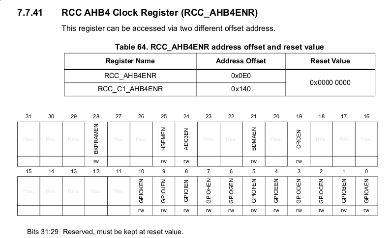
Enabling the clock for GPIO port D was as easy as writing 0b1000 to to the RCC
register, which thankfully, STM created a macro for.
RCC->AHB4ENR |= RCC_AHB4ENR_GPIODEN;Since pins 8 and 9 were used for RX and TX on GPIO port D, those also had to be enabled. Given that these pins were used by the USART driver, they would have to be set in 'alternative' mode which would allow the hardware to use it as an I/O device.
The GPIO Pin register looks as follows:
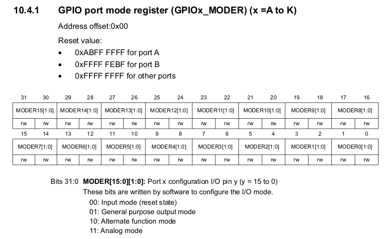
Since alternate mode is done by setting the flags for a pin to 10 we need to set bits 16:17 and bits 18:19 for GPIO pins 8 and 9 respectively.
The first thing we do is clear the current pin mode, and this can be done by setting the two bits for each pin to 0.
The easy way to clear pins 8 and 9 would be the following:
GPIOA->MODER &= ~(0xF0);Given that 0xF0 is the bit sequence '11110000', flipping it would give '00001111' (and a 1 in every bit from 20-31). This would make sure to maintain the state of all pins that were not pins 8 and 9.
While this would work to clear the pins, I decided to write a function to clear any pin, as this could be used later in my GPIO library. The function is rather simple, and it looks like so:
void GPIO_Mode(GPIO_TypeDef* port, int pin, enum GPIO_MODE mode)
{
    port->MODER &= ~(3 << (2 * pin)); // clears the GPIO pin
    port->MODER |= mode << (2 * pin); // sets GPIO pin mode
}
The clearing algorithm works by writing a 3 (0b11) in the two bits that are used to set each pins mode. Since each pin uses two bits, the bit offset is twice the pin number. e.g: pin 3 is in bits 6 and 7 so multiplying 3 by 2 will give us the shift of 6 we need to clear the bits.
Very similarly, the pin mode writing algorithm takes the pin mode and shifts it over by the pin number multiplied by 2. The pin mode is a simple enum in which each value represents the proper integer number to set the pins to get that mode.
enum GPIO_MODE {
    RESET = 0,
    INPUT = 0,
    OUTPUT = 1,
    ALTERNATE = 2,
    ANALOG = 3
};
Setting USART Channel 3
In order to set up the USART on the STM32, the USART clock, data bit length, parity checking, stop bit length, and mode had to be set.
Setting the data bit length was done using control register 1 (CR1), the layout of which can be seen in Figure 3
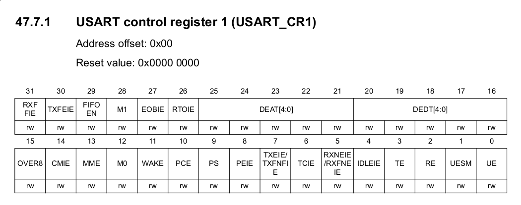
The data length was set using bits 12 and 28 (M0 and M1). In this case to keep things simple for now I decided to stick with a data length of 7 bits. In order to set the USART to 7 bit mode, both M0 and M1 need to be set to '0'.
Since both these bits clear on powerup, I didn't have to worry about setting either of these.
Setting up parity is done using a couple registers, but in our case we didn't want to use parity, so we just had to make sure a '0' was written to bit 10 (PCE). This disabled parity altogether, although if we wanted to set whether or not parity was even or odd we could use bit 9 (PS). Setting this bit to '0' would check for even parity, and '1' for odd parity.
The default stop bit length is 1 bit which is a pretty sane standard anyways, so I didn't bother changing anything about the stop bit length.
The last thing to do was update the baudrate of the USART chip. This was done using the USART's BRR register which can be seen in Figure 4.
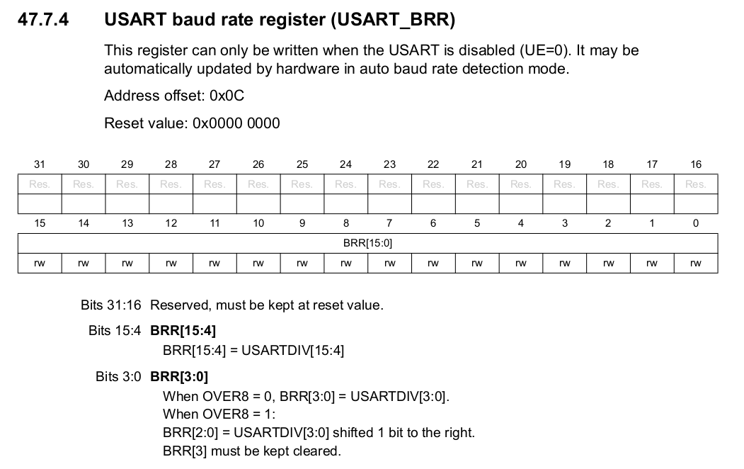
Okay, now that I've gotten this far it's probably time to tell the truth. I haven't fully managed to get USART working on my board, and I think it is something to do with how I'm setting my baud rate. There are an awful lot of clock sources on this board and the documentation doesn't exactly state which clock should be used or how to access that clock value.
I even enabled the USART3 clock using
RCC->APB1LENR |= RCC_APB1LENR_USART3EN;So if I'm gonna be honest, I don't have much of a clue how to fix this.
Enabling the USART is easy enough though, all one has to do is set the TE, RE, and UE bits (3, 2, and 0 respectively). So to enable the transmit, receive and the USART itself, it's a rather simple line of code:
usart->CR1 |= (USART_CR1_TE | USART_CR1_RE | USART_CR1_UE);In this example usart is a USART_TypeDef* that points to the USART port
being modified.
Final Thoughts
Setting up GPIO on the STM32 is rather straightforward and works just as you'd expect, I tested the GPIO using a couple jumper wires and some LEDs just to confirm that my errors were in my USART initialization and not that of my GPIO.
I must be missing something very obvious while initializing my USART 3 port, but I'm still stumped nonetheless. I'll look more into it in the upcoming weeks, maybe even try another port with physical pins.
November 15th, 2018
Finding the STM32-H743ZI resources
For some goofy reason, STM decided to make it near impossible to find the datasheets for all their recent chips. Also, many of them are hidden behind paywalls.
Also, instead of just providing simple header files for their chips, STM now gives the "cube" libraries, and HAL drivers. Instead of being basic and lightweight, these drivers are so ridiculously bloated it's not even funny.
Just to give an idea, I downloaded a "basic" set of examples for the Nucleo H743ZI. These were the packaged "cube" drivers I mentioned. This "small" set of examples was around 1.5GB, which is absolutely absurd for a set of examples, especially for an embedded systems development board.
Just to be clear, I don't dislike STM, in fact I like their products very much, I'm just a bit upset at the direction they seem to be going with their products lately. Everything is moving closer and closer to a subscription-based model where your dev. board won't actually be your dev. board.